
Introducing Runtime Micro's free WYSIWYG PWM application. It generates C++ code for Arduino Timers 1, 2, 3, 4 and 5. This works for Nano, Uno and Mega2560!
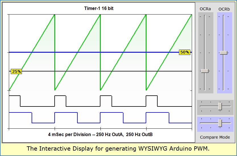
Using selections you make (Clock, Timer and Mode) along with your desired Frequency, the application shows a depiction of your PWM waveforms. Those same waveforms will appear on an oscilloscope hooked to your ARduino MCU port pins (after you upload the code of course).
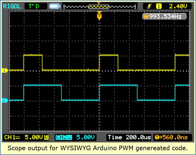
Yes, its a WYSIWYG tool even a beginner can use to create PWM at a desired frequency and duty cycle. What shows on the display will also show on your O-Scope! See next image...
Immediate PWM Feedback
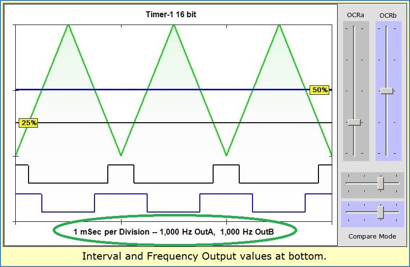
Notice those vertical slider controls on the above image upper right side? They adjust PWM Duty-Cycle percent. At lower right the horizontal sliders select Output-Compare modes. As you make changes, the display updates to show what you ordered-up.
In just moments, you can dial up a desired pattern and watch as Arduino compatible code is generated. Copy-paste the code to your Sketch, Upload and your Arduino PWM is ready to run!
Place your scope probes on the port pins to see your desired waveforms humming along at the Frequency, Period and Duty cycle you dialed up. Hardware PWM is easy this way!
Interval Interrupts
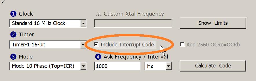
Sometimes you don't care about waveforms. Instead you need a precisely timed Interrupt to synchronize your code. No problem -- just check the Include-Interrupt checkbox and hit Calculate. A line of Interrupt code is created for any of 5 Timer choices. An Overflow-Interrupt fires each time your Timer completes a count cycle.
ISR Prototype with Vector
Included as a comment to the right of your Interrupt code-line, is a C++ Prototype of the vectored ISR your interrupt will call. If you don't already have that call coded in your Sketch, it's a handy reference for copy and paste.
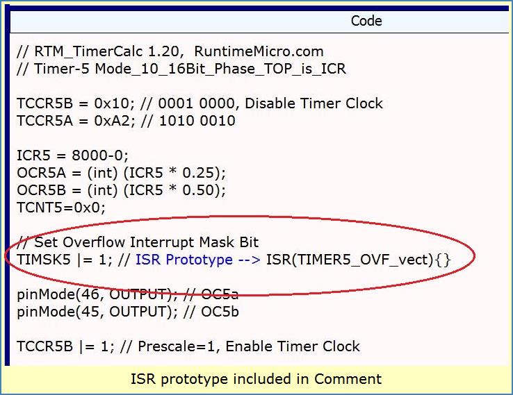
You'll likely place this ISR code after any #includes but ahead of Setup(). All 5 Timers are handled. Only the Overflow type Interrupt is included in RTM_TimerCalc output for now.
Arduino PWM Modes
RTM_TimerCalc uses a small subset of the many Timer Modes available. You'll get adjustable frequency Phase and Fast PWM for both 8 and 16 bit Timers. And you get one CTC mode for the 16 bit Timers. That adds up to 2 (8-bit) and 3 (16-bit) Modes -- across a selection of 5 possible Timers.
Pins, Pinmodes and Comments
RTM_TimerCalc generates PinMode code for each output waveform you choose. It adds comment-info identifying what PWM channel (a, b or c) is associated with which pin. You won't need to dive into a datasheet to work out what pin# needs to be set up as OUTPUT. This is true for pins on Nano, Uno and Mega2560 -- across Timers 1 thru 5.
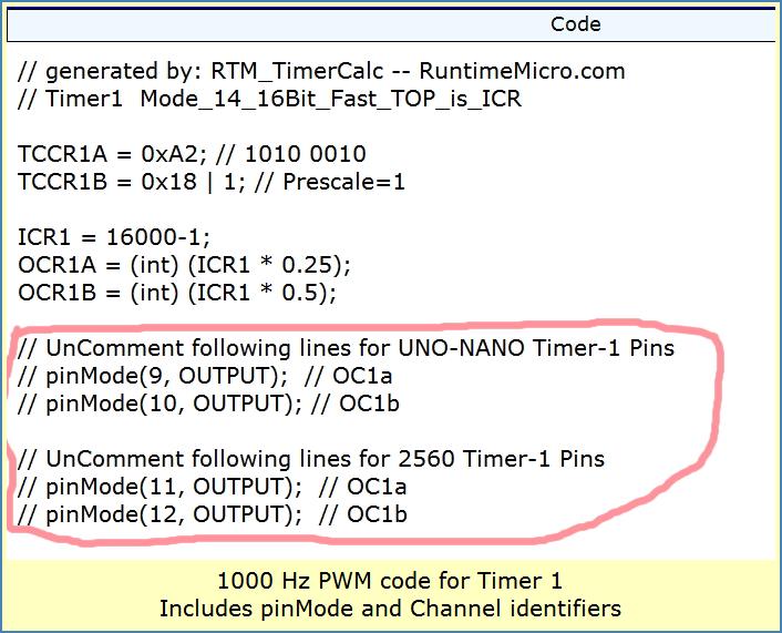
Image Path: /sites/default/files/Page-Images/Project/pinMode_Lines.jpg
Alt Text: Image shows code output for pinMode and channels identifiers
Prompts And Warnings
To ensure a smooth experience, the App. prompts you quickly thru the easy steps of choosing Clock, Timer and Waveform mode. Click the Calculate button and you'll see the resulting code. Edit a new Frequency or Time-Interval and press Calculate -- you're quickly ready to copy-paste to your IDE.
If you made a mistake, you'll hear a bleeping sound. Be sure you check the Report-Window for hints about what's going wrong. You may need to change to a different Timer or use a different frequency -- it happens.
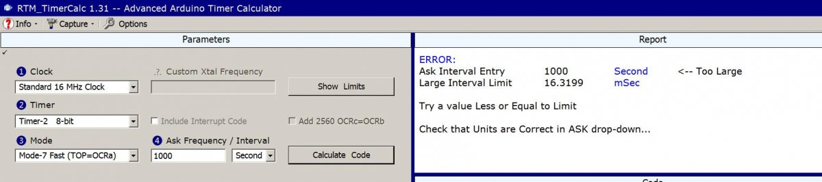
Sometimes your Arduino PWM parameters can NOT be made to work. And sometimes desired output is far away from what you requested. Read the Report-Window and consider accordingly. There are limits on what the hardware can do. You may need a 16-bit Timer if using an 8-bit at time of message.
Frequency or Interval
You start off with a default frequency of 1000Hz. Its easy to click a dropdown to change from Hz to mSec (frequency or time interval). And its up to you to edit that 1000 Hz value to whatever you need. Then hit Calculate.
If you hear no bleeps and see no warnings, you're good. Check the Frequency and Interval outputs at the bottom of the Waveform Display. They should match what you expected. If not, go back and check your inputs.
Arduino PWM Limitations
One not-so-obvious problem is when a counter divide-N value is below 100, you no longer have a Duty-Cycle resolution of 1 percent or better! The first release did not address this failing. Version 1.20 and later gives you fair warning about low PWM resolution and low Phase resolution in mode-12 CTC.
For example, if I ask for a 4-MHz frequency in Fast-PWM, I lose a lot of PWM resolution. In the first version, Duty-Cycle was not predictable using the interactive WYSIWYG display! But in version 1.20 and after, the WYSIWYG sliders adapt to the limited step-size for PWM or Phase Shifted square waves.
Mathematically speaking, we must realize a counter divide-N value below 100 will result in Duty-Cycle step sizes greater than 1%. And ff the divide-N value is less than 180, we'll get Phase-Shift step sizes greater than 1 degree. The good news is you are warned and forced to use only legal slider settings (in version 1.20).
Final Thoughts
Even if you're brand new to Arduino (Nano, Uno or Mega2560), you can quickly generate working PWM or Interrupt C++ code. The Interactive Display shows output waveforms and Duty-Cycle choices with summary Frequency and Interval info at bottom. This is an easy way to develop a viable PWM plan for your Arduino project.
VIDEO includes v1.4 info: https://youtu.be/UAnTXTELnpo
Look for the Download Page listing from HERE
Have fun generating custom PWM waveforms using RTM_TimerCalc.
Lee